The torque sensors from ATO are already traceably adjusted and tested in the factory. As an option we offer manufacturer calibration of the sensor.
Manufacturer calibration the manufacturer calibration involves checking sensor data against traceably calibrated measuring instruments. A range of measurement points are taken in this calibration. Manufacturer calibration produces a calibration report
DKD calibration DKD calibration involves calibrating the sensor in accordance with DKD directives in a calibration laboratory monitored by the DKD. With this calibration we define the measurement uncertainty of the sensor. Please contact us for further information.
Recalibration
Recalibrate the sensor after 26 months at the latest. Shorter intervals are recommended in the following cases:
- Sensor overload
- After repair
- After improper use of the sensor
- when required by quality standards
- where there is a specific traceability requirement
Test Sequence
The test sequence for drawing up a test certificate on torque transducers includes the following steps:
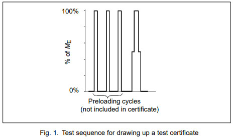
- Preloading to nominal torque three times in order to deal with settlement effects.
- Measuring the output signal at the load steps specified for the respective transducer with increasing torque (ascending series of tests).
- Measuring the output signal at the load steps specified for the respective transducer with decreasing torque (descending series of tests).
This sequence is carried out separately for clockwise and counterclockwise torque. It is illustrated in Fig. 1 for a torque transducer for which the number of specified load steps is two. In certain types with especially high levels of accuracy a larger number of load steps will be tested.

Contents of the certificate
To go into detail, the test certificate for torque transducers shows the following characteristic quantities separately for clockwise and counterclockwise torque:
- The measured output quantity delivered by the torque transducer at the load steps laid down in the test sequence
- Sensitivity
- Linearity deviation
- Linearity deviation including hysteresis
- Relative reversibility error
The measurement sequence includes the following steps:
- Preloading to nominal torque three times.
- Measuring the output signal at the load steps specified for the respective calibration with increasing torque (ascending series of tests).
- Measuring the output signal at the load steps specified for the respective calibration with decreasing torque (descending series of tests).
- Repeated measurement of the output signal with increasing torque (repeatability torque measurement).
- Re-mounting the transducer in a different situation in the calibration machine.
- Preloading in the new situation.
- Measuring one ascending and one descending series of tests in the new situation (reproducibility measurement).
- Re-mounting the transducer, preloading it again and carrying out a further series of tests in ascending and descending order in yet a third situation and in still more if necessary (reproducibility measurement).
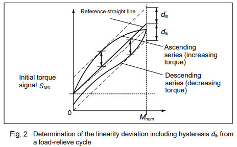
The linearity deviation including hysteresis can also be interpreted as half the width of the tolerance band that is symmetrical about the reference straight line (see Fig. 2). The only difference to the procedure for the determination of the linearity deviation dlin is that the load cycle here includes also the measurements at decreasing torque. This difference takes effect on both the calculation of the reference straight line and the deviations from the reference straight line.

To determine this value, proceeds as described below:
- The transducer is preloaded with counterclockwise torque in three load cycles from zero to 100 % of the nominal torque and back to zero torque. The purpose of this preloading is to eliminate the influence of mounting like settling of bolts and smoothing of contact surfaces.
- One load cycle with counterclockwise torque and recording of the respective values for the measurement signal at the predefined load steps (when testing during production these steps are at torque 0 %, 50 %, 100 %, 50 % and 0 % of Mnom.
- The torque transducer is preloaded with clockwise torque in three load cycles from zero to 100 % of the nominal torque and back to zero torque.
- One load cycle with clockwise torque and recording of the respective values for the measurement signal at the predefined torque steps.
- The best-fit straight line is calculated according to the above definition, separately for clockwise torque and counterclockwise torque • The amount of the maximum deviation from the best-fit straight line is determined separately for clockwise torque and counterclockwise torque.