The liquid viscosity measurement system designed in this paper is an improvement on the original rotary viscometer: on the one hand, a rotary torque sensor is used as the torque measurement element, and the measurement speed can be adjusted for fluids with different viscosity gradients. Thus, a relatively large viscous moment is ensured, the influence of the resistance moment fluctuation on the measurement result is reduced, and the measurement accuracy and reliability are improved. On the other hand, a temperature measurement and control system integrated with the outer cylinder is designed, which can meet the requirements of viscosity measurement at any set temperature in the range of room temperature to 200 ℃. In addition, based on Labview, the relevant control program, operation and display interface are written, which makes the automation and controllability of the measurement system higher.
1 Design of Liquid Viscosity Measurement System
The liquid viscosity measurement system designed in this paper is mainly composed of two parts: one is the viscosity measurement part, and the other is the temperature measurement and control part. Through the analysis of the coaxial cylindrical viscosity measurement principle and the temperature measurement and control principle, the viscosity measurement part mainly includes the following components: drive unit, torque measurement unit, rotational speed measurement unit, measurement drum unit, data acquisition and processing unit And the corresponding software and program control unit. The temperature measurement and control part mainly includes temperature measurement and control elements, signal acquisition and processing units and corresponding program control units.
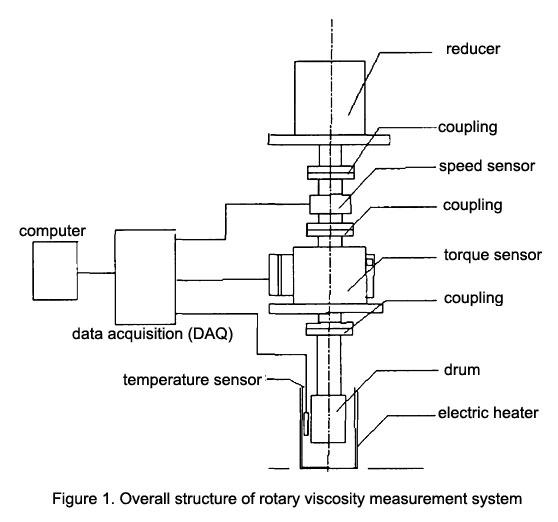
The overall architecture of the system is shown in Figure 1.

The inner drum is driven by the motor to rotate in the liquid to be measured. During the measurement process, the rotational speed of the inner drum and the viscous torque received are detected by the corresponding sensors. The temperature sensor signal together with the torque signal and the rotational speed signal are collected by the data acquisition unit. Then the collected signals are uploaded to the host computer, and the measurement results are displayed on the computer display interface through program processing, or output control signals to related components to complete some program control.
2 Technical Research of Power Drive Mechanism
It can be seen from the measurement principle of the rotational viscometer formula η=KM/n, that a measurement speed n needs to be provided when measuring the viscosity. Smooth speed regulation in a wide range, this function is realized by the speed regulating motor. Through the analysis of the measurement principle of the rotary viscometer, it can be known that when measuring the viscosity of the liquid, the liquid to be measured should be injected into the gap between the inner and outer tubes first, that is to say, when the driving mechanism drives the inner cylinder to start to rotate, it is affected by a viscous torque, so the driving mechanism is required to have a large enough driving torque to ensure that the inner cylinder can be started with a load and driven to a predetermined speed.
To sum up, the driving mechanism of the rotary viscometer must have two basic conditions: a sufficiently large driving force; the other is to be able to achieve smooth speed regulation in a wide range.
The driving mechanism selected in this paper is a speed-regulating motor, and the starting torque of the motor can reach 837mNm, which can meet the requirements of the rotary viscosity measuring instrument for the starting torque. Secondly, this type of speed regulating motor can realize stepless speed regulation in the range of 0~300r/min.
3 Technical Research on Torque Measuring Mechanism
In the previous rotary viscometers, the torque measurement devices mostly use flexible shaft torque measurement systems such as hanging wires, tubular springs, and disc springs. The viscous torque acting on the sensor will cause them to deflect at a certain angle. The measurement of liquid viscosity is accomplished by detecting the deflection angle. This type of torque sensor has two major disadvantages: first, the accuracy of the torque measurement device is not high, especially after a long period of use, it is difficult to ensure a high measurement accuracy. Secondly, this type of torque measuring element is relatively fragile, and if the torque changes sharply, it is easy to cause damage to the measuring element. Therefore, it is particularly important to choose a torque measuring element with high reliability and accuracy.
The torque measuring element selected in this paper is a shaft to shaft rotary torque sensor. The sensor uses strain gauge electrical measurement technology, that is, using the strain effect and piezoresistive effect of metal materials. For a wire of length L, cross-sectional area S, and resistivity ρ, its resistance is
R=ρL/S
Under the action of external force, the metal wire will undergo a certain degree of mechanical deformation, which will cause its resistance to change, which is the resistance strain effect of the metal material. Under the action of external force, the crystal lattice of solid materials will also change to a certain extent, which will lead to changes in its resistivity, which is the piezoresistive effect.

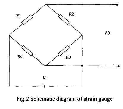
The main measuring part in a torque sensor is the strain bridge attached to the elastic shaft, as shown in Figure 2. Provide a constant voltage U to the strain bridge, and the strain gauge will deform to a certain extent under the action of torsion, so that its resistance R will change, which is reflected in the change of the output voltage V0. The conversion yields a frequency signal proportional to the torsional strain. The sensor range is 0-0.5Nm, the corresponding frequency value is 10kHz~15kHz, and the corresponding torque value can be obtained by detecting the frequency value.
The rotary torque sensor selected in this paper has the following characteristics:
- Signal output can choose pulse square wave or 4~20mA, 1~5V and other standard signals, and can also be equipped with digital torque meter;
- High detection accuracy, good stability and strong anti-interference ability;
- Continuous measurement of torque can be achieved without repeated zero adjustment;
- Both static torque and dynamic torque can be measured;
- Small size, light weight, simple and convenient installation, only need to provide 24V DC power supply, it can output pulse square wave frequency signal or standard transmission signal whose impedance is proportional to torque.
The main performance indicators of the rotary torque sensor are shown as fllows:
Torque error: <±0.5%FS
Sensitivity: 1±0.2mV/V
Output frequency signal: 5kHz~15kHz
Temperature drift on zero: <0.5%F.S/10℃
Current consumption: <200mA
Repeatability: <±0.2%FS
Negative rated torque: 5kHz~10kHz
Positive rated torque: 15kHz~10kHz
In the viscosity measurement system, the acquisition card needs to collect the torque sensor signal, the rotational speed sensor signal and the temperature sensor signal. The rotary torque sensor used in the viscosity measurement device outputs the pulse signal, the sensor range is 0~0.5Nm, the corresponding pulse signal The frequency value is 10kHz~15kHz, so if the number of pulses output by the sensor within 1s can be collected, that is, the output frequency of the sensor, the torque value corresponding to the sensor can be obtained by calculation.
The data acquisition card used in this article utilizes a USB bus-powered multifunction data acquisition (DAQ) module that maintains high measurement accuracy at high sampling rates.
The module provides 18 analog signal inputs, 4 digital inputs, 4 digital outputs and 2 counters/timers. It is specially designed for portable applications or applications with strict space requirements. It can be directly connected to a computer through a data cable to achieve plug-and-play, which minimizes its configuration and setup time, while the signal transmission line Can be connected directly to the screw terminals on the capture card, which greatly reduces cost and simplifies signal connection.
4 Software Design of Liquid Viscosity Measurement System
4.1 Introduction to Labview software
The data acquisition card is directly connected to the USB interface of the computer through the data line, and transmits the signal output by the sensor into the computer. The reading, analysis and processing of the sensor output signal are realized by the program written by the Labview software.
4.2 Program design of the torque measurement part of the system
It can be seen from the content of the previous chapters that the torque sensor is used in this paper to complete the torque measurement during the test process, and the torque value measured by the torque sensor corresponds to the frequency of the sensor output signal. Therefore, the focus of the program design of system torque measurement is to obtain the frequency of the electric pulse signal output by the torque sensor. In the program, the number of electrical pulses collected per unit time is obtained through a timed loop, and then the torque value is obtained.
The implementation of the block diagram is mainly divided into four basic processes: the first process is to configure the virtual channel, and select the counter you want to use in the configuration virtual channel function; the second process is to start the task, and the start task function node is responsible for the task Start; the third process is to read the current value of the counter in a loop, and set the time interval through the software in the loop to achieve continuous data acquisition and processing; the last process is to clear the task, and the node is responsible for releasing the allocated system after the signal acquisition ends. resource.
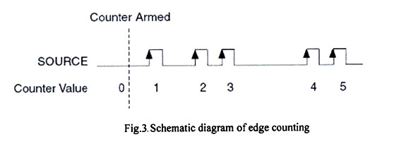
The output terminal of the torque sensor signal is connected to the counter input terminal of the acquisition card. There are two counters for the data acquisition card selected in this article. Therefore, when creating a virtual channel node in the program, first select the counter ctr0 to be used. In the VI selector Select the counting method of the counter to be edge counting, and then configure the counter. The current default value is set to 0, and the rising edge counting is selected at the counting time. There are three options for the counting direction: up counting, down counting and external control counting.
Figure 3 shows a schematic diagram of the edge counting process of the counter. From Figure 3, it can be seen that with each edge transition of the electrical pulse signal, the counter automatically increases by one after the rising edge.

In this paper, the number of electrical pulses per unit time is used to represent the frequency, and then the torque value is obtained accordingly. Therefore, the total number of pulses collected in one second is subtracted from the total number of pulses in the next second to obtain the increment of the number of pulses collected in one second. The shift register is used to complete the data processing of the pulse signal. After the shift register is added to the While loop structure, the shift register will appear in pairs on both sides of the loop structure box, and the right terminal will appear after each loop is completed. The corresponding pulse number is stored, and the last stored pulse number will be moved to the left terminal in the next cycle, and the difference between the two stored pulse numbers is the accumulated value of the pulse number in this time period. A timer is added to the While loop in the program to realize the timing loop of the program block. The loop timing period is set to 1000ms (that is, 1s), so that the data difference between the two terminals of the shift register is the pulse collected within 1s. number, that is, the output frequency of the pulse signal. Because the corresponding frequency of the sensor is 10kHz when the torque is 0 Nm, and the corresponding frequency is 15kHz when the torque is 0.5Nm, so the number of pulses in 1s needs to be subtracted from the number of pulses when 0 Nm is 10000, and the difference needs to be multiplied by the corresponding torque sensor. Accuracy can get the corresponding torque value. 0 Nm~0.5 Nm corresponds to 10kHz~15kHz, that is, 1Hz corresponds to 0.0001, so the sensor accuracy is set to 0.0001.
5 Chapter Summary
This paper mainly introduces the hardware design of the viscosity measurement system and the corresponding software implementation. The working principle of the viscosity measurement part is analyzed, and the overall structure of the system has been constructed. The work completed in this chapter mainly includes two parts: one is to complete the various functional modules according to the market price and performance indicators of the relevant measurement components. Finally, the speed-regulating motor was selected as the driving device, the incremental rotary photoelectric encoder was used as the rotational speed measurement unit, the rotary torque sensor was used as the torque measurement part, and the solid-state relay was used to complete the circuit control. Pt100 RTD and silicone rubber were selected. The heating element is used as a temperature control element, and the design of the measuring drum is also completed; the second is to complete the program design of the three parts of torque measurement, rotational speed measurement, and temperature measurement and control based on Labview, and construct the overall program operation and display interface.