1. Background
At present, advanced manufacturing represented by large ships, large aircraft, large equipment and wind power industries is developing rapidly. Bolts, as one of the main connection methods of equipment, are used in many parts, such as: hubs, gearboxes, wind turbine blades, propellers, etc. Therefore, the entire industry attaches great importance to the safety performance of high-strength fasteners. With the rapid growth of bolt usage, the control of bolt quality has also become one of the most important links in the development and design of fasteners in the industry.
2. Test Requirements
A customer proposes an experimental program that involves bolt preload and preload torque measurements on bolts of various types of connection materials. In addition to being able to accurately measure bolt preload and preload torque simultaneously, the system requires reliable accuracy and long-term stability. The test program is designed to verify the required preload force and preload torque specifications for fasteners to ensure product reliability while facilitating installation.
3. Products
3.1 Dual flange rotary torque sensor
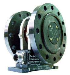
Basic parameters:
- Accuracy: 0.1%
- Measuring range: ±0.1~±600 kNm
- Excitation voltage: 12-30VDC
- Output signal: USB2.0, RS232, RS485, ±5V, ±10V, 4-20mA, Ethernet
3.2 Dual flange reaction torque sensor
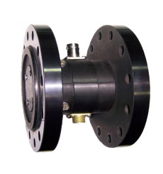
Basic parameters of dual flange reaction torque sensor:
- Accuracy: 0.1%
- Measuring range: ±0.1~±300 kNm
- Excitation voltage: 12-30VDC
- Output signal: USB2.0, RS232, RS485, ±5V, ±10V, 4-20mA, Ethernet
3.3 Ring force sensor
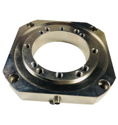
Basic parameters:
- Accuracy: 0.5%~1%
- Range and size: non-standard customization can be provided according to different needs of customers
- Excitation voltage: 5-10V
- Output: 1~2mV/V
- Overload protection: 150%
4. System Composition and Function
As shown in the figure above, the measuring system for the force and torque of threaded fasteners consists of five devices: motor (1), dynamic torque sensor (2), nut clamping mechanism and reaction torque sensor (3&4), annular preload sensor (5).
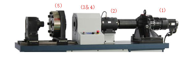
The large range rotary torque sensor connects the motor to the nut slot through the flange structure to measure the torque applied to the bolt during assembly. The nut clamping mechanism and the reaction torque sensor are fixed by the intermediate support frame to measure the torque parameters of the fixed end of the nut. An ring force sensor is attached to the end of the mechanism to measure the axial preload during bolt and nut preload. The accompanying software enables customers to record and plot data. Excel-compatible files then allow further manipulation and analysis of detection data.
Ultimately, the system configured by dynamic torque sensor, static torque sensor and force sensor provide the customer with the ability to accurately monitor the preload and torque of tightened fasteners.
5. Data Processing
5.1 Transmitter
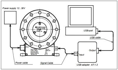
The transmitter mainly decodes the digital serial code signal output by the torque sensor into various signals. The output signals of different types of transmitters include frequency, analog, USB2.0, Ethernet, RS485, RS232, etc. Choose USB output transmitter to directly connect to the computer, and use it with the data acquisition software on the computer. Transmitter for torque sensor can form a data acquisition, waveform analysis and processing system in various fields such as laboratories and product quality inspection centers, and can also form an industrial production process monitoring system.
5.2 "Transmitter" software functions:
- MODBUS network master with integrated Т26, T36 and T46 decoders.
- Remote LAN access to other measurement complexes.
- Real-time digital data filtering.
- Real-time display of measurement data in digital and graphic form 5. Real-time recording of measurement data to hard disk.
- The software supports up to eight different types of transmitters at the same time.
- View recorded data in numerical and graphical form.
- Set program options.
- Correct transducer parameters by writing to EEPROM.
- Develop user's own data processing program with DLL and program interface.
- Channel synchronization, which refers to the common (synchronized to the PC precise clock) channel start and time adjustment during processing of incoming data using precomputed correction coefficients.