With the development of combine harvesters, people put forward higher requirements for the automation of agricultural machinery. Most of the domestic combine harvesters rely on the operator to observe the feeding amount to adjust the speed. The automation level is not high, and it is easy to cause the threshing drum to be blocked due to the excessive feeding amount, causing the machine safety belt to burn out. Since the feeding amount cannot be directly measured by the device at present, the indirect measurement method is adopted. In this paper, the torque of the threshing drum shaft is selected as the monitoring amount. Under normal circumstances, the drum torque is proportional to the load. When overloaded, the torque increases accordingly. After exceeding the rated range, the auger shaft is easily stuck, and the torque of the drum shaft can timely and accurately reflect the load of the threshing drum shaft. The traditional method of measuring torque is mainly to install a tension roller as a sensor on the tight side of the transmission belt. This method has a complex system structure, low accuracy, large hysteresis and easily affects the life of the belt. Today, torque sensors have high accuracy, fast frequency response, and good reliability, and a variety of torque sensors have appeared on the market. Based on the measurement of the torque of the drum shaft, this paper expounds the application selection and installation methods of several common torque sensors on the combine harvester, and the comparison of their advantages and disadvantages.
1. Determination of Torque Sensor Range
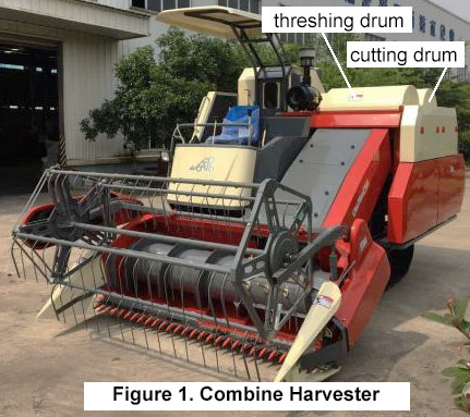
The high-speed rotating motion of the engine is decelerated by the pulley, sprocket and reducer, and transmitted to the intermediate shaft, which drives the threshing drum shaft and the cutting drum shaft to rotate. The crops are repeatedly beaten and turned by the rotating spikes between the drum concave screen and the rolling cover grass guide bars, and then separate the grain and straw. Figure 1 is a product physical map of the combine harvester.

When the drum shaft is blocked, the load is the largest. According to the on-site measurement, the maximum load is: F=3 kN, the radius of the drum is 280 mm, and the maximum torque is: T=FR=3×280=840 Nm. Therefore, the standard range of the torque sensor is selected as 1000 Nm.
2. Torque Sensor Structure and Principle Analysis
There are many types of torque sensors and different classification methods: according to the connection method of the sensor, they can be divided into shaft type, flange type and tightening type; according to the different detection methods, they can be divided into strain gauge torque sensor, magnetoelectric type Torque sensor, magnetoresistive torque sensor, etc. The structure of the threshing drum shaft is shown in Figure 2. According to the specific structure and size of the shaft, different types of torque sensors are selected and analyzed.

2.1 Shaft or flange torque sensor

For shaft torque sensors or flange torque sensors, two sets of couplings or flanges are required to be installed between the sprocket and the shaft, where the sprocket is the power source and the shaft is the load. In order to keep the changes to the overall structure of the harvester as small as possible, in contrast, the axial length of the flange torque sensor is small, and the axial distance of the flange torque sensor for 1000 Nm range is 60 mm. Although the size is small enough, the gap between the end face of the harvester drum and the end face of the sprocket is only 50 mm, which cannot be installed directly, and the size of the shaft needs to be redesigned. At the same time, in order to ensure the rationality and stability of the transmission, the following three methods need to be adopted:
- Rearrange the shaft system on the same plane to make room for the installation range of the torque sensor in the axial direction.
- Reduce the length of the drum method to keep the sprocket position unchanged;
- set the sensor inside the drum.
Method 1 increases the overall scope of the harvester, but at the same time it needs to redesign multiple drive shafts, which increases the cost. Method 2 reduces the volume of the threshing drum, reduces the efficiency of threshing, and affects the overall rhythm section cutting speed. Method 3 It is necessary to redesign the structure of the drum and the drum shaft so that the structure can meet the installation of the sensor.
2.2 Sprocket torque sensor

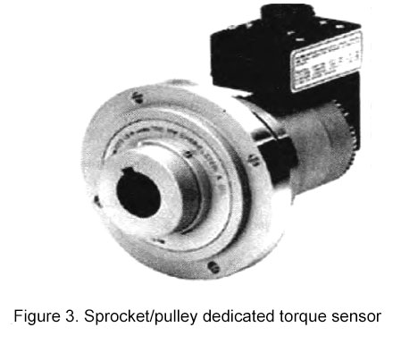
Figure 3 is a sprocket/pulley dedicated torque sensor. It can be directly connected to the shaft end as a part of the shaft, so there is no need to redesign the structure of the drum and other transmission shafts as a whole, and it does not affect the layout of the overall shaft system. Only the shaft end of the drum shaft is required to ensure that the shaft and the torque sensor can pass Key connection, reliable overall structure and easy installation.
2.3 Snap Ring Rotary Torque Sensor
Both the strain gauge type and the non-contact torque sensor belong to the intervention type, that is, it must be used as a part of the transmission shaft, which limits its application range. Now there are snap-ring strain-type torque sensors on the market. You only need to clamp the sensor on the shaft or install it on the side of the shaft without disconnecting the shaft system, which brings great convenience to measuring torque in actual working conditions.
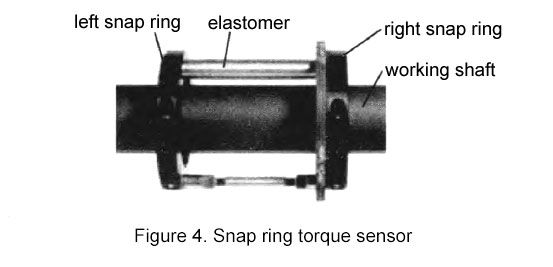
The schematic diagram of the structure of the snap ring sensor is shown in Figure 4. Two semi-circular snap rings are used, which are connected by bolts. Under the huge pre-tightening force of the bolts, the two semi-circles can be tightly attached to the measuring shaft. Due to the effect of torque, there must be a relative torsion angle between the two snap rings.

An elastic body is fixed between the two snap rings, and the deformation of the elastic body can describe the magnitude of the torque that the entire shaft bears. When calibrating this sensor, it is necessary to simulate a shaft that is exactly the same as the working shaft size, material, heat treatment method, etc. The effective shaft length is usually greater than 100 mm.
| Type | Flange torque sensor | Sprocket torque sensor | Snap Ring Torque Sensor |
| Feature | No bearing, can run at high speed, high measurement accuracy, good stability, strong anti-interference, the installation is between the shafts. | It can run at high speed and has high precision, and the installation position is located at the end of the shaft. | No need to disconnect the shaft system, suitable for high torque, small clearance, medium and low speed measurement. |
| Size | Big | Big | Small |
| Current state | Mature product | Special for sprockets | New product |
| Standardization | Yes | Yes | No |
| Price | >1500USD | >12000USD | >1000USD |
3. Sensor Advantages & Disadvantages Comparison and Selection
Torque measurement of combine harvester threshing drum shafts is possible using any of the three non-contact torque measurement solutions described above. According to the different of the measured object, use environment and measurement effect, there are still big differences in the non-contact torque measurement solutions realized by these three key technologies. Through the detailed comparison of the solutions, Table 1 lists their advantages and disadvantages It provides a technical reference for the sensor selection application of non-contact torque measurement.
From the analysis in Table 1, it can be seen that although all three schemes can realize the torque measurement of the drum shaft. In terms of performance, the flange-mounted measurement method is more direct, easy to install, smaller in size, and relatively cheap in price, without the need to rearrange the structure. If it is used for long-term testing, an uninterrupted power supply module can be used to achieve long-term uninterrupted work. At present, the non-contact, simple and reliable structure of the flange torque sensor based on the wireless signal transmission module is in the stage of rapid development and will be more and more favored by the market.
4. Conclusion and Outlook
With the continuous development of domestic productivity and science and technology, the degree of automation of agricultural machinery will be higher and higher, and the automatic feedback system needs to use various types of sensors to detect dynamic parameters of different parts. For agricultural machinery, the working environment is relatively harsh, the selected torque sensor must be stable and reliable, and try to use mature sensors on the market. Several common rotary torque sensors analyzed in this paper can also be used for other aspects of combine harvester detection, such as the torque detection of the cutter drive shaft, the torque detection of the header drive shaft and the torque detection of the intermediate output shaft. By detecting the dynamic torque of these key spindles in real time, it will be beneficial to analyze the power consumption and load status of each component, so as to reasonably design the transmission ratio, automatically distribute the power and speed of each axis, and reduce the overall power loss of the harvester.