To obtain ideal and accurate test data, we must pay attention to the mechanical installation of the torque sensor. For this mechanical installation problem, end users or field installers tend to ignore it.
According to the needs of the test application, selecting the appropriate torque sensor installation method, selecting the correct coupling and high-standard mechanical assembly on site can avoid or reduce the test error caused by the introduction of additional loading force in the entire test chain. At the same time, it can also avoid the damage of the torque sensor caused by the extra loading force. The dynamic torque sensor mainly adopts the installation methods of ordinary key connection, flange connection, and clamping shaft sleeve by optical shaft cooperation.
As for how to install the rotary torque sensor correctly, we will discuss the problem from the following aspects:
- Axial center deviation
- Adjustment of Coaxiality
- Coupling Type
- Torque sensor installation method
- Examples of torque sensor installation
- Other issues to consider
1. Axial Center Deviation
Before installing the torque sensor, adjust the coaxiality first. Although the elastic coupling can compensate the installation error, once the shafting is in working state, the deformation under load or the vibration deformation caused by high-speed operation will aggravate the different coaxiality. In order to make the coupling work within the compensable error range, and in order to prolong the life of the coupling, the coaxiality must be adjusted to a better range.
Different couplings are selected for rotary torque sensors with different installation structures, which greatly affect their accuracy and life.
2. Adjustment of Coaxiality
Due to different machining datum, in the assembly process of the two shaft ends, there will inevitably be axial center deviation problems, including radial deviation, axial deviation and angular deviation. See figure 1.
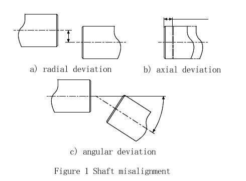
In order to minimize the axial center deviation, we must use suitable elastic couplings. Flexible coupling manufacturers generally provide specific information on couplings. Including torque range and allowable axial center deviation range.
3. Coupling Type
Common couplings include rigid couplings and elastic couplings. Rigid couplings do not have the ability to compensate for coaxiality errors, while elastic couplings have the ability to compensate for coaxiality errors, including axial errors, radial Orientation error, angle error. After the rigid coupling connects the two shafts, if the coaxiality is not good, the shaft will be forced to bend and deform, and additional loads will be applied to the supporting parts such as bearings, which will increase the deflection of the shaft system, and will increase the system vibration at high speed.
The elastic coupling is divided into half coupling (Single-Flex) and full coupling (Double-Flex). Single-Flex coupling only compensates axial and angular deviation, while Double-Flex coupling can compensate axial error, radial error and angular difference. Common Single-Flex couplings are single-diaphragm couplings, and the rest are fully coupled.
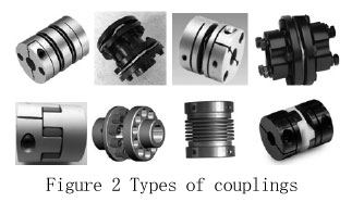
In figure 2, the first two in the first row are Double-Flex couplings, and the last two are Single-Flex couplings. The second row is a curved jaw coupling, an elastic pin coupling, a bellows coupling, and an Oldham coupling as followed. Select the appropriate coupling according to the manufacturer's sample and compensation value.
4. Torque Sensor Installation Method
For torque sensors with different installation forms, the selection of the coupling is different.
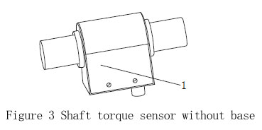
4.1 Shaft torque sensor without base
Figure 3 is a torque sensor without a base. The housing 1 in Fig. 3 does not play a supporting role, and the torque sensor is in a suspended state. There are two installation methods for this shaft torque sensor without base, one is to use two single-flex couplings, such as single-diaphragm couplings, similar to the structure of the second double-flex coupling in the first row of Figure 2. Second, the torque sensor adopts rigid connection at one end and double-flex coupling at the other end, such as elastic pin coupling, curved jaw coupling, double diaphragm coupling, etc.
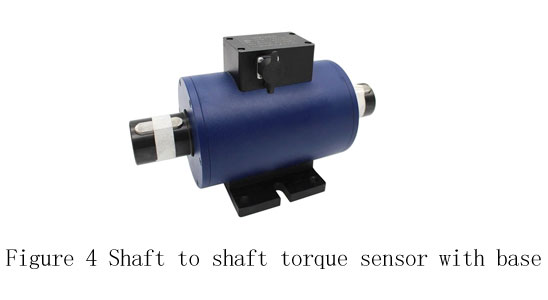
4.2 Shaft to shaft torque sensor with base
As shown in Figure 4, when installing, the base of shaft to shaft torque sensor is fixed on the pedestal with screws, and the two ends of the torque sensor are supported by bearings. Both shaft ends are fixed constraints, and there are angular deviation, radial deviation and axial deviation. So each shaft end both require a double-flex coupling, such as a double-diaphragm coupling.
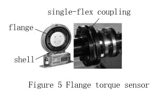
4.3 Flange torque sensor
This torque sensor consists of two flanges and a shell. The flanges and the housing are separated. The flanges are connected with the shafting, and the shell is fixed on the pedestal for data transmission. The selection of the coupling is similar to the shaft to shaft torque sensor without base. That is, when one end is rigidly connected, the other end adopts a double-flex coupling, such as a double-diaphragm coupling. Or both use single-flex coupling. Such as figure 5, it uses two single-flex couplings.
To sum up, when the shaft end of the dual flange rotary torque sensor is fully constrained, a double-flex coupling is selected. If the shaft end is free, two single-flex couplings can be selected, or one end of the coupling can be rigid connection, and the other end uses a double-flex coupling.
5. Examples of Torque Sensor Installation
5.1 Here are a few right installation methods:
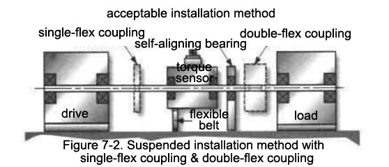
As shown in the follow figure 6-1, figure 6-2, there are 2 types of installation methods. One is the "fixed" installation of the sensor, and the other is the "suspended" installation of the sensor. Fixed installation, the bottom of the sensor is rigidly connected to the test bench. The shaft and coupling weights are loaded on the sensor housing through the sensor internal bearings. Suspended mounting is the opposite, with the shaft supporting the sensor housing through the sensor's internal bearings.
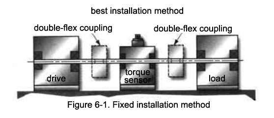
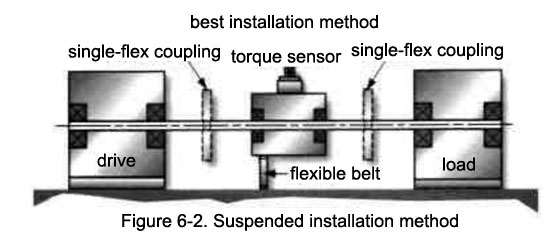
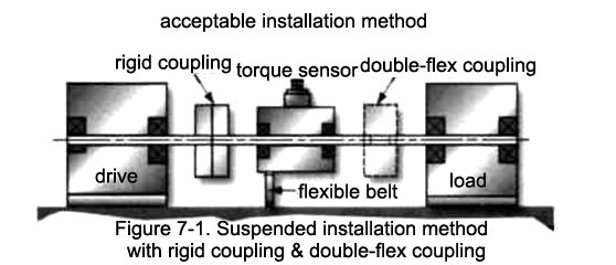
Figure 7-1 and figure 7-2 demonstrate several correct and common installation methods.
When the two shafts are connected, if the radial direction and angle are fixed, a double-flex coupling must be used. If a single-flex coupling is used, it will cause a large test error and even damage the sensor. Single-flex coupling can only compensate for radial deviations by bending the entire shaft.
If a single-flex coupling is used, there must be one and only one of the two shaft ends that can move in the radial direction without restraint. Only in this case a single-flex coupling can compensate for angular deviations. If this is the case, use a double-flex coupling will cause large vibration and cannot achieve the effect of elastic coupling.
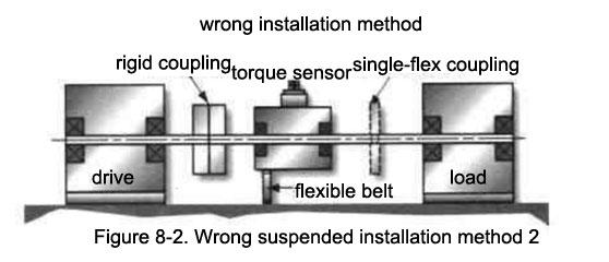
5.2 Here are a few wrong installation methods:
Pic 8-1. The single-flex coupling cannot compensate for the radial deviation. So the wrong installation will cause a large disturbance of the shaft and introduce a large test error, and will greatly reduce the service life of the sensor, especially increase the bearing wear.
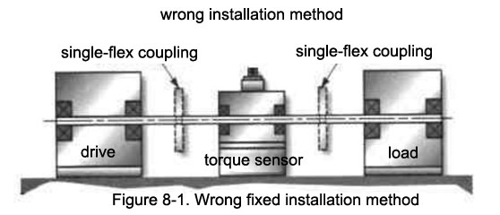
Figure 8-2, in this installation, the use of rigid couplings will force the entire shaft to bend. We have no way of knowing how much the bend is. However, it is conceivable that if the axis deviation is large and all components are rigid, the disturbance loading will become larger and larger as the temperature rises. Disturbance loading can greatly reduce the service life of the sensor.
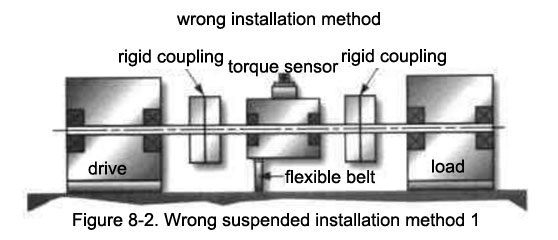
Figure 8-3. Although this installation is an improvement over the previous case as it uses a single-flex coupling. However, the entire axis is still affected by the additional disturbance loading force.
6. Other Issues to Consider
6.1 Evaluate the moment of inertia of rotating parts throughout the test chain.
Due to the moment of inertia, the reaction torque will be generated when the state of the rigid body changes: M= J*B (B is the angular acceleration).
It is important to prevent the sensor from being overloaded instantaneously due to its excessive rotational inertia, especially micro torque tests.
The axial/radial/perturbation loading involved in evaluating both ends of a torque sensor must be less than the limits listed in the sensor catalog.
6.2 System vibration
Vibration will not only introduce additional errors to the torque test, but also cause certain damage to the sensor or other test equipment, so we must frequently check the vibration of the test bench.