The output mechanical energy of the pump reflects the efficiency of the pump, and the output mechanical energy is directly reflected in the output torque of the pump shaft. Therefore, it is of great significance to accurately and reliably test the torque of the pump shaft for analyzing and understanding the output of the pump and whether the working state is normal.
The torque test method commonly used in engineering is the transmission method, that is, the method of testing the torque according to the changes in physical parameters such as deformation, stress or strain generated by the elastic element when transmitting torque. The most common elastic element is the torsion shaft. This method is easy to apply and with high precision.
Due to the high speed of the water pump, it is difficult to transmit the deformation, stress or strain signals generated when the shaft is twisted by wire. The wireless sensor testing technology can better solve this problem.
Wireless detection technology is an advanced detection technology which is based on wireless sensor network technology, and integrates computer technology, communication transmission technology, information technology and traditional detection technology. Wireless torque detection adopts wireless network for data transmission, which solves the problem of difficulty in drawing out signal lines on the rotating shaft and improves the reliability of data transmission. At the same time, this method also has the advantages of convenient installation and operation.
1 Principle of Wireless Torque Measurement
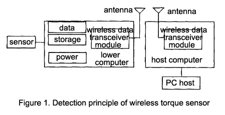
The principle of wireless torque detection is shown in Figure 1. It is mainly composed of torque sensors (strain gauges pasted on the water pump shaft), upper computer, lower computer and PC host. The upper computer and lower computer replace the data signal transmission lines and data collector.
The strain signal of the torque sensor (strain gauge) is directly transmitted to the lower computer, and the lower computer collects, processes and stores the signal from the torque transducer in real time according to the requirements of the PC host, and adopts a specific wireless network transmission protocol at a certain data transmission rate. The upper computer performs various operations required by the PC host.
2 Application Examples
The total planning area of the irrigation area of an irrigation project is 16.4 × 10⁷ m2, the design irrigation area is 11.5 × 10⁷ m2, and the developed land is 75.3 × 10⁷ m2, including 66.6 × 10⁶ m2 of cultivated land and 8.7 × 10⁶ m2 of forest land, and the actual irrigation area is 53.3 ×10⁶ m2, the design water intake is 7.716 6 × 10⁷ m3, and the current annual water diversion index is 5 × 10⁷ m3. The irrigation area is pumped into the irrigation area by a 4-stage pump station for irrigation. The test object is the No. 1 and No. 5 pump shafts of the secondary pumping station of the large-scale pumping station in the irrigation area, and its power is tested. The main nameplate parameters of the tested unit (P is rated power; n is rated speed; U is rated voltage; I is rated current; Q is flow; H is head; η is efficiency; cosΦ is power factor) as follows.
(1) No. 1 pump unit
Motor: P=2, 000 kW, η=750 r.min-1, U=10, 000 V, I=134 A, cosΦ=0.9.
Pump: P=1, 800 kW, Q=5 940 m3h-1, H=75.8 m, η=740 r.min-1, η=90%.
(2) No. 5 pump unit
Motor: P=400 kW, η=1 485 r.min-1, U=10, 000 V, I=28.7 A, cosΦ=0.86.
Pump: P=355 kW, Q=1 260 m3h-1, H=75.2 m, η=1480 r.min-1, η=85%.
2.1 Test method
By measuring the torque M on the coupling or the rotating shaft, combined with the speed n of the shaft, the power of the shaft is obtained by P=2πnM. Due to the high speed of the unit, it is difficult to lead out the signal line on the rotating shaft, so the SG404 wireless test system is used.
According to the theory of material mechanics, for a shaft subjected to pure torsion, the principal stress direction on the surface is at an angle of 45° and 135° with the axis, and the principal stress is equal to the maximum shear stress. Therefore, when the coupling of the tested pump is attached with a strain gauge at an angle of 45° along the axis, when the torque M acts, the strain gauge produces strain, and its variable has a linear relationship with the torque M. Calculated as follows:
ε45°=ε135°=8M/πD3G*[1/(1-d4/D4)]
Where ε is the strain; G is the shear modulus of elasticity; D is the outer diameter of the shaft; d is the inner diameter of the shaft.
Connect the strain gauge with the SG404 wireless node. When the shaft is subjected to torque, the SG404 wireless node sends the strain signal generated by the strain gauges with a specific wireless network transmission protocol at a certain data transmission rate, and the wireless gateway will receive The received signal is processed and recorded by PC host.
2.2 Test results
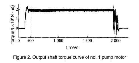
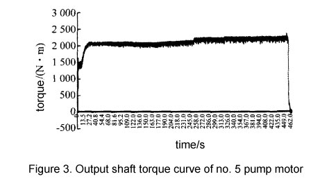
The test conditions are: start-up→run (750 r.min-1 for No. 1 pump, 1, 480 r.min-1 for No. 5 pump)→shutdown. The torque test results of each pump motor output shaft under the test conditions are as follows:
1) The shaft torque of No. 1 pump is 2, 0266 Nm when it runs steadily at 754 r r.min-1 (Fig. 2), and the corresponding calculated value of shaft power is 1599 kW.
2) The shaft torque of No. 5 pump is 2, 131 Nm (Fig. 3) when it runs stably at 1 489 r.min-1 speed, and the corresponding calculated value of shaft power is 332 kW.
2.3 Analysis of results
It can be seen from the torque curve of the motor output shaft in Figure 3 that the No. 5 pump runs smoothly throughout the whole process, and the output power is 332 kW, which is slightly lower than the nameplate power (355 kW). The output power of the No. 1 pump is 1, 599 kW, which is lower than the power on the nameplate (1 800 kW). At the same time, the torque curve (Figure 2) of the No. 1 pump during the shutdown process is abnormal. During the shutdown process, abnormal vibration occurs for 100s, and the torque variation is -5, 781~ 29, 779 Nm, the maximum sudden change is 1.47 times of the rated torque. Factors such as unit installation size deviation and too short shutdown time may cause abnormal torque curves during startup and shutdown. It is necessary to further debug and inspect the unit to improve its operating state.
3 Conclusions
- The above application examples show that the use of wireless torque sensor technology can accurately test and record the actual output torque of the pump motor shaft in real time, and the test results are accurate, which is of great significance for understanding and analyzing the running state of the pump.
- Wireless torque detection adopts wireless network for data transmission, which has the advantages of convenient installation and operation, and better solves the problem that the wired detection technology is difficult to lead out signal lines on the rotating shaft. It also improves the reliability of data transmission.