Having high-precision testing instruments is particularly important for the reliability of motor test data, which is directly related to the authenticity of the test results. With the further deepening of international cooperation and exchanges and the continuous improvement of motor testing accuracy requirements, there will be more testing institutions and enterprises using ATO torque sensors. Today, we will tell you about the use of ATO torque sensor ATO-ZJ-AF in motor testing.
I. Sensor Performance Introduction
The ATO-ZJ-AF torque sensor measuring torque and rotational speed is a dual flange torque sensor. It has a compact design and takes up very little space. The high lateral protection allows the connecting shaft to be directly connected to the flange without additional support shafts and can withstand higher dynamic loads. Its extremely high torsional rigidity eliminates torque resonances, due to flanges operate without bearings and slip rings and are therefore completely maintenance-free. It adopts a modular design structure, its rated torque is 20/50/100/200/500/1000/2000/5000 Nm, the accuracy can reach 0.1%FS, and the Speed signal is 60-2000 pulse/turn. The measured value is output through voltage and frequency signals, and the converter with ATO can be directly connected to the computer, thereby making subsequent data processing and analysis more convenient.
II. Mechanical Connection
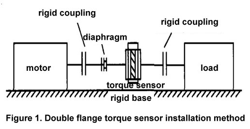
Figure 1 shows the ATO-recommended installation. In order to avoid the additional bending moment caused by the deformation of the sensor, the motor under test, the sensor and the load must have good concentricity during installation, and there should be a certain distance between the two half-couplings (see Table 1) .
III. Electrical Connection
ATO-ZJ-AF rotary torque sensor has only one electrical connecter. Sensor plug is connected to ATO-ZJ-A-F/V(I) converter for torque/speed transmission.
ATO-ZJ-A-F/V(I) is a signal converter used with ATO rotary torque sensor, which can convert the voltage or frequency signal sent by the sensor into a standard signal and display it on the torque meter. It can also be connected to the computer through the D.Sub port on the converter to directly collect the test data on the computer. Then carry out the subsequent processing of the data. The wiring of ATO-ZJ-A-F/V(I) is shown in Figure 2.
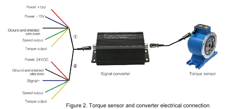
When connecting the signal line, pay attention to the direction of the connector. After connecting, screw on the locking screw to achieve better shielding effect and prevent the measurement signal from being disturbed. ATO's low-capacitance shielded cable is recommended for the connection between the sensor and the measuring amplifier. If you want to extend the cable, make sure that the contact resistance at the joint is low, and it has good insulation and shielding. Do not place the power line and control line of the measurement cable motor in parallel (if this requirement is not met, the distance between them must be ensured not less than 50 cm).
IV. Recommendations
The installation method in Figure 1 is suitable for the case where the motor under test is not replaced. If the motor under test needs to be replaced frequently, other installation methods are required. The main reason is that the sensor is suspended without support, and the two ends are rigidly connected to the motor under test and the load. When replacing the motor under test, due to the self-weight of the sensor and the weight of the coupling, plus the deformation of the elastic diaphragm, the motor end of the sensor under test sags. Over time, it will affect the accuracy of the sensor. In addition, due to the installation of the elastic diaphragm, the center height of the tested motor, load, and sensor cannot be aligned, and disturbance will occur under the action of the diaphragm after the motor rotates. The suspension of the torque sensor makes it easy to collide with the tested motor and load when it is installed and centered.
The new installation method is shown in Figure 3:
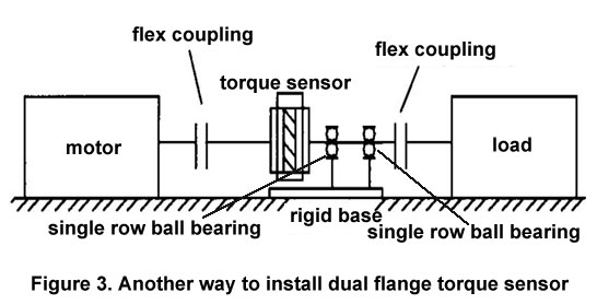
The shaft at the load end of the sensor is slightly longer and supported by two bearings. The bearing adopts a single row ball bearing to reduce the axial clearance and minimize the sag at the other end, so that the whole system maintains clearance, minimizes the sag at the other end, and makes the entire system The system remains level.