1 Introduction
Internal combustion engines have been a major power source throughout the history of ground vehicles. The introduction of electronic ignition and fuel injection systems in the 1980s have given the engineers far more capability of engine control than before. Since then, both fuel economy and emissions have improved, but still more progress can be expected in the future. One of the limitations in engine control development lies in the scarce on-line information about the controlled process, the combustion.
Some sensor technologies are already in use in modern engine control systems (EMS) to provide specific combustion information. Oxygen sensors mounted in the exhaust pipe enable closed-loop air- fuel ratio control and piezoelectric knock sensors mounted on the engine block enable closed-loop knock control. However, more combustion information is constantly required to enable more precise engine control. Several other methods exist for combustion monitoring, such as cylinder pressure sensing, engine speed measurement, ionisation current sensing or crankshaft torque sensing. None of these technologies have yet met all the demands from the motor industry in terms of cost, performance, reliability or durability, nor is it known whether or not a single method has the capacity to meet future requirements. The pressure sensor seems like the preferred choice since many of the desired combustion properties can be derived from cylinder pressure. However, the in-cylinder environment has this far proved too hostile for any pressure sensor to be precise, durable and cheap enough for mass production. The other three sensor technologies suffer less from hardware limitations, but rather from lack of knowledge about the information content contained within their signals. The research continuously advances in all methods.
The torque sensor is evaluated in this paper since it is an interesting alternative to the other sensors, not only for combustion sensing, but also for other purposes like traction and gear-shift control. It is a very durable piece of equipment due to its simple principle, non-contact properties and ability to perform well in hostile environments. The goal here is to present a method for the closed-loop control of the spark advance of a spark-ignited engine for maximum fuel efficiency based on torque measurements.
1.1 Measures for combustion phasing
The combustion phasing describes the timing of the combustion process in relation to the position and movement of the piston. With such a measure available on-line, it is possible to arrange a closed-loop control of the start of combustion (SOC), which makes it possible to obtain the highest possible thermal efficiency of the engine. Several measures for combustion phasing have been defined and can be estimated using different sensor technologies:
- The peak pressure position (PPP), is the position in crank angle where the maximum pressure occurs.
- The 50% mass fraction burned (MFBso) is defined as the crank angle where half of the injected fuel is consumed by the combustion.
- Tthe 50% pressure ratio (PRso) is calculated by taking the quotient between the combustion pressure and the motored pressure. PRso is then the position which is half-way between the lowest and the highest value of the quotient (in a region around top-dead centre).
- The 50% torque ratio (TR 5o) is a new measure for combustion phasing and essentially analogous to the pressure ratio, but is calculated in the torque domain instead. The theory of torque ratio is briefly reported in this paper.
1.2 Available sensors
To measure combustion properties in a more direct fashion, several types of sensors have been utilised such as:
- In-cylinder pressure sensors are very good for acquiring direct information about the combustion. It is well known what could be done if high-resolution pressure measurements were available. Due to the price of the sensors at the time of writing, it is not feasible.
- Ion current sensors measure the conductivity of the combustion gas, which typically varies over time. Thus, it is sensitive to the conductive properties of the gas. The sensor is used in production today for detection of misfire and knock.
- Angular speed measurements are available in engines today but needs to be of higher resolution to be able to use for crank angle resolution estimations. Since angular speed sensors are commonly available it is an attractive sensor which has been used extensively.
- Engine block accelerometers are very common and sturdy. It is possible to estimate several properties of the combustion process by placing the accelerometers cleverly while having a good model for how the vibrations are transferred through the engine block. Typically this method requires heavy calculations.
- Crankshafi-mounted torque sensors is another alternative, which is studied in this paper. By measuring the absolute torque at one point in the crankshaft it is possible to estimate combustion properties.
I.3 Torque sensor
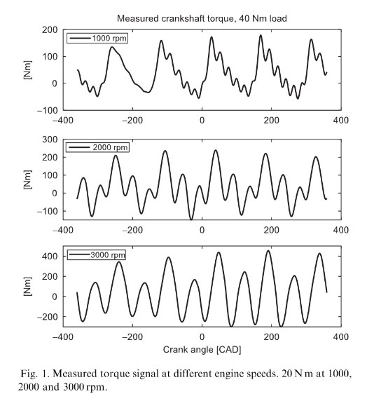
The torque sensor consists of two parts, a sensor shaft and a housing. The housing holds a primary and a secondary winding, which are connected to the sensor electronics. The sensor shaft is a segment of the crankshaft with two modifications. The material of the shaft is carefully selected to have specific magnetic properties and copper strips are attached on to the surface of the shaft to permit only certain directions of magnetic field to propagate. An alternating current through the primary winding induces a magnetic field in the shaft. The magnetic field is linked by the copper strips and induces a current in the secondary windings. The stress in the shaft material caused by the transferred torque in the shaft changes the magnetic properties of the shaft material, and hence the induced current in the secondary windings changes. The signal quality is good with low noise, see Fig. 1, which shows measured torque data.
1.4 Crankshaft effects
The crankshaft connects all piston movements of the internal combustion engine into one rotating motion and transforms the gas pressures from the combustions to torque on the output axis of the crankshaft. The crankshaft has a spring behavior and will store some energy when transferring the torque. When the stored energy is released it induces oscillations in the whole crankshaft. The rotary torque sensor in the experimental engine is located between the last crank throw and the flywheel and measures the sum of the torque contributions of all cylinders and the crankshaft energy.
The crankshaft can be regarded as a multiple-input- single-output (MISO) dynamical system, considering the transformation of individual cylinder torque contributions to the measured total torque output. The crankshaft dynamics introduce oscillations in the output torque which are not present in the cylinder inputs. Fig. 1 illustrates the problem. At 1000 rpm the influence of resonances is low and the measured signal looks like the sum of the cylinder torques, but at 3000 rpm the resonances totally change the torque signal. Andersson and McKelvey proposed a method on how to handle the crankshaft dynamics, which is used and described briefly in this article.
2 Control Architecture
The architecture for controlling the combustion phasing based on torque measurements requires both an estimate and a desired value of the combustion phasing. The combustion phasing is selected as the controlled entity rather than the spark timing, since the optimal combustion phasing is less sensitive to changes in e.g. moisture and equivalence ratio compared to the optimal spark advance. According to simulations the optimal combustion phasing is less sensitive to flame angle variations in general. Therefore, the optimal set-point for the combustion phasing is easier to find for an extremum controller, which requires the assumption that the dynamics of the optimal position are very slow in comparison to the extremum-controller dynamics.
In the implementation of the control architecture the goal is to maximise the cylinder individual work, no considerations have been made concerning emission levels. Thus, the possibility to optimise one property of the combustion is demonstrated and it is up to the end-user to formulate a perhaps more relevant criterion.
The combustion-phasing controller consists of five independent and parallel PI-controllers, see Fig. 2. They are simple to use in a situation like this where no dynamics are present in the process, i.e. the combustion phasing between combustion cycles are uncorrelated for normal operating conditions. The set-point for the combustion controller is obtained from cither an extremum-seeking controller- which receives an estimate of the cylinder individual work together with the combustion phasing from the cylinder separation algorithm- or from the user itself, bypassing the extremum-controller entirely. The 50% Torque Ratio is used as a measure for combustion phasing.
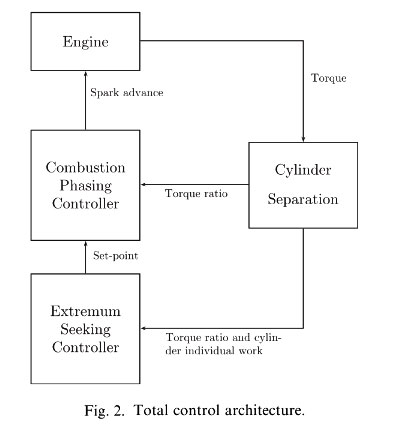
The combustion-phasing controllers obtain the torque ratio from a cylinder separation algorithm, which separates the original measured torque into the torque contributions from each cylinder. This process is described in more detail in Section 2.1.
The combustion phasing controller output is the spark advance, which has a non-linear relation to combustion phasing. Stability can be guaranteed since the non-linear rclation is monotonous. A stability analysis of the spark advance controller is presented in Larsson and Egardt (2004).
Extremum-seeking control
Extremum-seeking controllers belong to a family of methods which try to set one or several process parameters in such a way that some observable objective function is maximised. It is also required that any changes of the objective function are on a much slower time scale than the actual extremum- seeking dynamics. To develop further, the following is required:
- An observable objective function must be available. The indicated work depends on the combustion phasing and is chosen as objective function for each of the five cylinders. It is assumed that the indicated work can be optimised independently for each cylinder.
- The operating point in the objective function must be controllable with respect to the process parameters used. The spark advance is used as controllable parameter for each of the cylinders.
- The dynamics of the objective function must be on a much slower time scale than the extremum-secker dynamics. This requirement is fulfilled by operating the engine in steady-state. For the application to be even more useful it is necessary to be able to handle transients also, but this has not been considered so far.
3 Experimental Set-up
The experimental equipment is based on a standard five cylinder Volvo V70, spark-ignited gasoline engine with a torque sensor integrated in the crankshaft. The engine is coupled to a Schenck W 150 dynamometer. The engine has an adjustable intake camshaft for variable valve timing (VVT). By changing the VVT angle it is possible to change the internal EGR fraction, and thereby change the burn rate properties of the combustions. A PC collects torque and cylinder pressure data via data acquisition cards (DAQ), performs on-line calculations and communicates spark timing via a CAN-bus to the EMS. The custom measurement and control software can handle engine speeds up to approximately 2500 rpm in real-time control, where the limit in computational resources is reached. The software is not optimised in any way and a better implementation should give an increased performance.
Collected data
This article uses four data sets, see Table 1. The data sets B to D are used to present one experiment each. Data set B, used in Section 5.1, is about changing internal EGR, data set C, used in Section 5.2, is about individual cylinder control, and data set D, used in Section 5.3, presents results on extremum-seeking control. Data set A was collected during a sweep in spark advance from 45 CAD BTDC (before top dead centre) to 10 CAD BTDC. It is used for showing the relation between the spark advance, the individual cylinder IMEP and the combustion phasing.
| Data set | Engine speed | Load | Specication | Purpose |
| A | 2000 | 25 | lgnition sweep from 45 to l0 CAD BTDC - 3000 cycles | To visually verify optimal combustion phasings |
| B | 2000 | 25 | VVT-step - 775 cycles | Testing how well the combustion phasing controller copes with changes in internal EGR |
| C | 2000 | 25 | Switching from identical ignition angles to identicalcombustion phasing - 366 cycles | Testing cylinder individual control |
| D | 2000 | 25 | Extremum-seeking control - 2789 cycles | Testing which combustion phasings are optimal |
4 Control Experiments
Three different experiments demonstrate the capabilities of torque sensor-based engine control:
1) In the first experiment_ the controllability aspect is addressed, proving that the combustion phasing can be detected and controlled by the system. An external disturbance is simulated which affects the burn properties, causing the combustion phasing to change. The system detects and reacts on the change in burn properties.
2) Second, the possibility to control each of the cylinders individually is shown by setting the combustion phasing to the same absolute value. All cylinders obtain individual and different spark angles depending on their burn properties.
3) The last experiment shows the self-calibrating capability of the system. The combustion phasing for each cylinder is optimised on-line to maximise the estimated cylinder individual work.
4.1 Experiment 1: step-response using internal EGR
The primary target for the controller is to choose an ignition angle such that the desired combustion phasing is obtained. Production EMSs of today use a feed-forward open-loop structure to control combustion phasing. Calibration of look-up tables requires a substantial amount of work to handle all kind of disturbances, which can affect the combustion process. Also, extra sensors are needed to detect the presence of disturbances such as moist air and residual gas fraction. This experiment demonstrates the convenience and possibility of measuring the combustion phasing when an unknown disturbance occurs.
One common disturbance is changes in burn rate. It is dependent of several things like air moisture, equivalence ratio, residual gas fraction and more. The VVT is used for creating such a disturbance. If the valve overlap in the gas exchange phase increases, burned gases are pushed back into the intake manifold. This leads to an increased fraction of burned (residual) gases and slower combustion and the controller must compensate by igniting earlier to maintain the desired combustion phasing. The valve overlap is changed in a step and the controller is not aware of the change.
Fig. 3 shows an example of the capability of the controller when changing the intake VVT-phasing. The third subplot shows the setting of the VVT-phasing, which is changed from 18° to 50° and back again. When the VVT-phasing is set to 50° the amount of residual gases increase substantially and the combustion rate slows down.
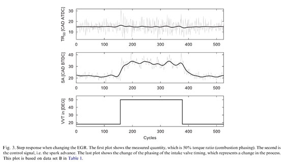
The first subplot shows the estimated torque ratio (combustion phasing) for the second cylinder. The set- point for the torque ratio is 15 CAD ATDC (after top dead centre). The thick line is a low-pass filtered version of the light grey measured data. The torque ratio does not change very much in a mean-value sense. It can be noticed that the combustion variability (noise level) increases during the higher VVT-phasing.
The second subplot represents the control signal, which is the spark advance in this case. It can be seen that the controller has to ignite earlier during the higher VVT- setting since the combustion rate is slower.
The conclusion of the experiment is that the combustion phasing can be estimated and is controllable, by the use of the described methods.
4.2 Experiment 2: cylinder individual control
In most of the engine management units in production today, all of the cylinders are ignited using the same spark advance. Unfortunately, it is not very common with identical combustion properties in all of the cylinders. The burn rate may differ between cylinders due to differences in air injection, residual gas fraction, etc. Individually optimised spark timings can lower the effect of imbalance between cylinders.
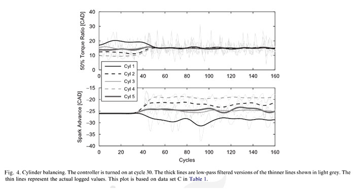
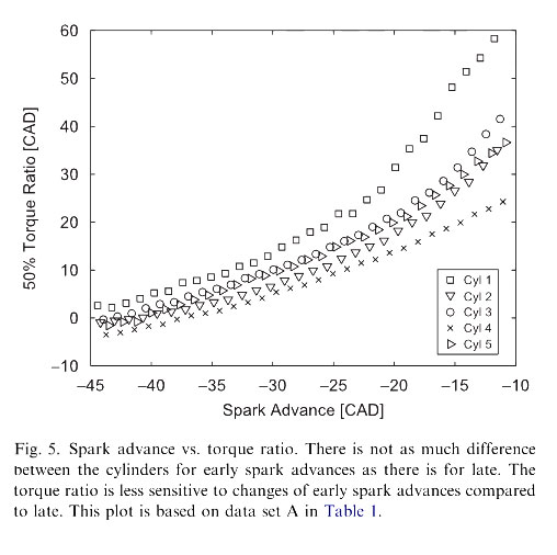
To demonstrate the possibility to run an engine with cylinder individual combustion phasing control the following experiment was designed. The engine is started with a constant uniform ignition angle, and after a while the combustion phasing controller is turned on to force all of the cylinders to the same combustion phasing; 15 CAD ATDC. The outcome of such an action is seen in Fig. 4. It can be noticed that one constant ignition angle for all of the cylinders leads to different combustion phasings. This can be understood by looking at Fig. 5 where the torque ratios estimated by the on-line algorithm are plotted versus the corresponding spark advance. There are some differences between the cylinders, which can be explained by both burn rate differences, and estimation bias phenomena.
4.3 Experiment 3: finding the optimal combustion phasing using extremum-seeking control
It is possible to locate the optimal combustion phasing for each cylinder by making an ignition angle sweep and based on that find a good set-point. In reality it might be of desire to continuously adapt the set-point during operation. It is also possible to compensate for bias in the combustion-phasing estimate due to imperfections in the estimation algorithm.
In Fig. 6, an example of an extremum-seeking controller in action is shown. It is looking for the combustion phasing, which gives the highest possible mean torque output. The optimal combustion phasings differ a bit, which is due to both differences in the cylinder burn rates and also estimation bias.
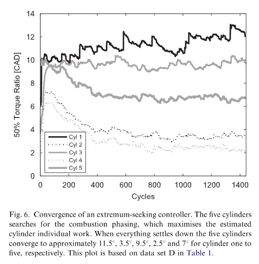
Fig.7 shows estimated combustion phasings from the real-time algorithm and IMEP estimated from cylinder pressure measurements. It can be used to check the validity of the optimal combustion phasing which the extremumseeking controller claims to have found, see Fig. 6. The first cylinder has an optimum around 11.5° and is represented by squares in Fig. 7. It is hard to tell whether this really is the optimal position since the function is very fat. For cylinder two (triangles pointing down) and four (crosses) it is much easier to see. Their optima should be at 3.5° and 2.5°, respectively and those values fit well. Cylinders three (circles) and five (triangles pointing right) also have quite flat functions but their estimated optima make sense.
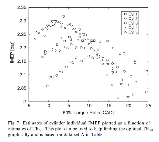
To conclude; the extremum-seeking controller is able to find a good value for the combustion phasing in order to optimise the cylinder individual IMEP. The fact that the IMEP values in Fig. 7 were calculated from, a different signal source (cylinder pressure) than the ones used by the extremum-seeking controller (crankshaft torque), shows that the controller actually finds the correct optimum.
5 Conclusions and discussion
The possibility to utilise a torque sensor for cylinder individual feedback control of combustion phasing using spark advance has been demonstrated.
Compared to a similar previous study this article has extended the implementation to cope with crankshaft dynamics. Thus, it is possible to run the engine at higher engine speeds by eliminating torsional resonances due to flexible crankshaft steel. The current implementation is limited to 2500 rpm in on-line operation due to limitations in computer performance, but theoretically there should be no limit.
The implementation has been extended with an extremum-seeking controller adding self-optimising functionality to the system. The implemented control system finds the accurate optimal combustion phasing individually for all cylinders, verified at constant engine speed and throttle angle. There are several issues that were not covered in the investigations, regarding the performance of the system. One is the needed sampling rate. Crank angle- based sampling was chosen to make the geometry functions of the engine known and predictable. The data was sampled at 1 CAD resolution, giving a rate of 6kHz at 1000 rpm. The interesting dynamics of the crankshaft appears below 500 Hz, indicating that a reduction in sample rate should be possible and reduce the computational load of the system.