1. Introduction
Mechanoluminescent (ML) microparticles mixed in a solid matrix can emit stress-induced visible light from a solid in response to mechanical stimuli, including tension, compression, friction, and fracture (such as cracking), which are referred to as ML phenomena. Typically, applications of ML microparticles, such as SrAl2O4:Eu2+ ,Dy3+ (SAO), have been used in a stress sensor applications successfully, in which these particles are applied to real-time visualization of the stress distribution of cracks, impacts, and ML light source generation. Kim et al. expanded their potentials of ML microparticles by providing a preliminary experimental study investigating the dynamic torsional response analysis of a mechanoluminescent (ML) material (i.e., ML paint with a mixture of SAO and transparent epoxy resin) and its application as a non-contacting automotive torque transducer. The working principle of this new torque measurement system can be described as follows: the visible light emission induced by torsional stress is measured directly using a luminescent sensor to convert into torque in the rotational shaft, as shown in Fig.1. Therefore, the only luminescent sensor is required to detect variation in the light intensity signature. One common type of luminescent sensors, a photomultiplier tube (PMT) sensor, can be used to convert the light intensity into a voltage output (i.e., a PMT output). The torque applied to a rotational transmission shaft was measured by sensing the ML intensity emitted from a ML paint mixed with SrAl2O4:Eu2+. ,Dy3+. This new functional material can, therefore, provide a new non-contacting means of measuring the dynamic torque applied to a rotating shaft. Although this study provided fundamental knowledge for the potential development of new non-contacting torque sensing technology based on ML intensity detection using the luminescent sensor, it has, however, been reCognized that this technology exhibits some critical technical limitations, such as insufficient sensitivity to ML intensity and the decay response of ML intensity, especially to a constant torque input.
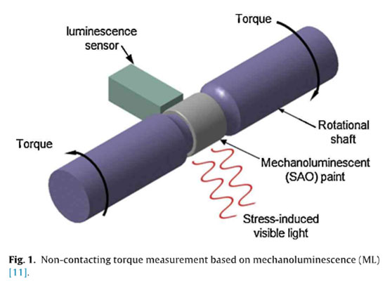
Therefore, the main objective of the present study is to provide a solution for developing a new non-contacting torque sensing technology. The initial issues inherent to the previous prototype torque transducer are resolved by using a different ML microparticle (ZuS:Cu), and its torsional dynamic response to the sinusoidal torque inputs is investigated in Section 2. Two hysteresis models (the semilinear Duhem model and the ad hoc heuristic model) are considered, and these two models are compared to characterize the loading rate-dependent characteristics of ML intensity emitted from ZuS:Cu in Section 3. Based on the proposed heuristic hysteresis model, a simple but effective hysteresis compensation method is developed to estimate the torque input from the ML intensity measurement, as described in Section 4.
2. Mechanoluminescence of ZuS:Cu
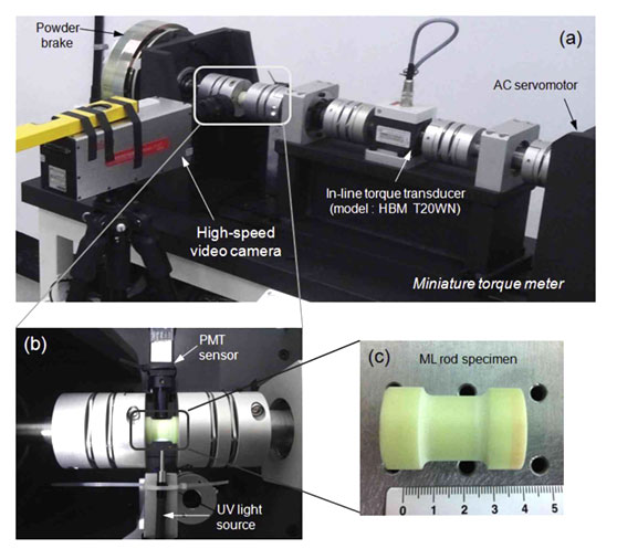
In the previous study, an aluminum transmission shaft coated with ML paint made with a hard epoxy resin was used to measure the dynamic torsional response. However, in the present study, a plastic ML rod specimen is manufactured to improve the sensitivity to ML intensity, as shown in Fig. 2. Acrylic resins (E= 3.2 GPa), a group of related thermoplastic substances derived from acrylic acid, are used to make a hard plastic rod sufficient to transmit torques ranging from 1 Nm to 50 N m. In addition, two types of microparticle [30% vol. SrAl2O4:Eu2+ ,Dy3+ (SAO) and ZnS:Cu powder] are mixed with the transparent acrylic resin to create a ML rod specimen, and this specimen is used to compare ML intensity characteristics. The visible light emission induced by torsional stress is measured directly using a PMT sensor module provided by Hamamatsu Photonics.
In the case of SAO, the specimen was exposed to 365 nm ultraviolet (UV) light for 5 min, and aged in the dark for 1 min to allow the long phosphorescence to relax to a reasonable level prior to loading of torque. A light intensity signature was emitted from a hardened ML rod where a powder of SrAl2O4:Eu2+ ,Dy3+ (SAO) was included as the single phosphor. If the ML rod is activated by the ultraviolet (UV) light source, hole trap levels immediately above the valence band in SAO will be constituted by Dy3+ ions after charge-transfer of the original energy. Photoexcitation of the Eu2+ activators creates hole emissions to the valence band, which are consecutively trapped by Dy4+. When a stress (or strain) is finally applied, they are then released and recombined with the Eu+ activators, which leads to an excited Eu2+ state followed by photon emission. Unlike the rod containing SAO, the ML rod specimen with ZnS:Cu microparticles has been continuously exposed to a 365-nm ultraviolet (UV) light source during the measurements. Although ZnS:Cu has the benefit of self activation by stress itself as well as UV source, ZnS:Cu microparticles basically showed relatively rapid decay in photo-luminescent (PL) and less ML response against applied load in the preliminary study, which implies poor possibility to be used as the non-contacting torque sensor for the industrial applications. To overcome these drawbacks, we have tried to maximize the variation of photon intensity by introducing the saturated activation condition while the measurement proceeds. As a result, the measured values included the combined effect of torque on PL and ML. Therefore, it might not be a conventional ML, but still could be categorized as one of varietal ML, because the luminescent phenomena were fundamentally used to sense the mechanical torque or stress. More specific and systematic investigations considering the con- current dual PL and ML variation induced by single mechanical action are currently under investigation on the basis of micro- mechanism approach.
An electric servomotor (model: Mitsubishi F -SP352, 3.5 kW) is used to drive the shaft, which rotates at a constant angular velocity of 21 rads-1 (200 rpm) determined by a speed controller. The load torque is produced using an electromagnetic powder brake (model: NKPB-5.0, 50 N m) controlled by DC voltage (0-24 V). The details of a miniature torque meter for dynamic torsional response analysis are described in a previous reference.
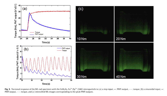
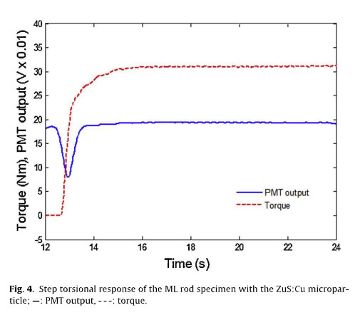
The dynamic torsional response of the ML rod specimen with a conventional micro particle of SAO to the slew-rate limited (step- like) input change and to the sinusoidal input is first examined to explain the preliminary experiment performed in the previous study. When a constant torque (i.e., a torsional load) of 30Nm is applied for about 26s, the ML intensity (ie.. the PMT output voltage) increased immediately, reached a peak, and then gradually decreased, as depicted in Fig. 3(a), which shows good agreement with previous studies investigating torsional and tensile specimens. The brightness difference corresponding to the peak PMT outputs proportional to applied torque can be identified from the intensified images photographed at a frame speed of 60 fps (Fig. 3(c)). Conversely, in this study, a sinusoidal input torque [T(t)= 20+ 10 sin(2π .0.5t)N m] is applied by controlling a powder brake. The PMT output appears to respond to a sinusoidal input without a phase delay (i.e., an in-phase input), but the peak magnitude gradually decreased with time (Fig. 3(b)). To resolve the decay issues in ML intensity when SAO serves as the microparticle (see Fig. 3), a new microparticle ZuS:Cu is pro- posed in this study. The torsional response of the ML rod specimen with new micro particle to changes in the slew-rate-imited input is measured in Fig. 4. When a constant torque of 30 N m is applied for about 13 s, the ML intensity decreased initially and then recovered.
However, when a sinusoidal input torque [T(t)=20+ 10 sin(2π .0.5t)Nm] was applied, the ML intensity responded with a phase delay, as shown in Fig. 5(a). Generally, this phenomenon can be characterized using the x-axis to display the applied torque input, which is called hysteresis loops between the torque input and the PMT output (the ML intensity), as shown in Fig. 4(b).
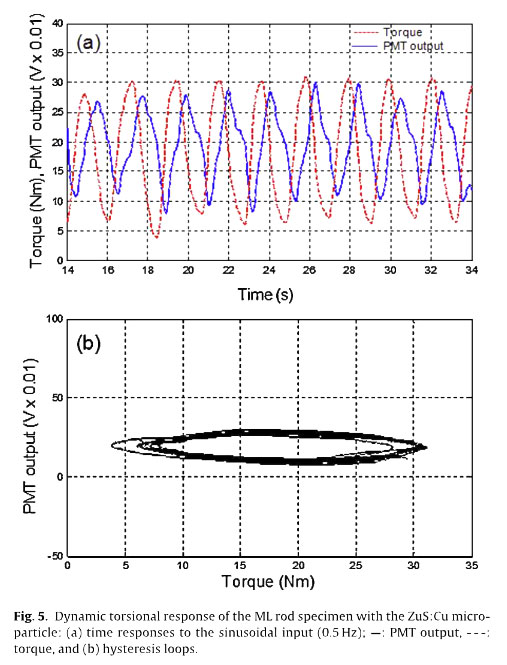
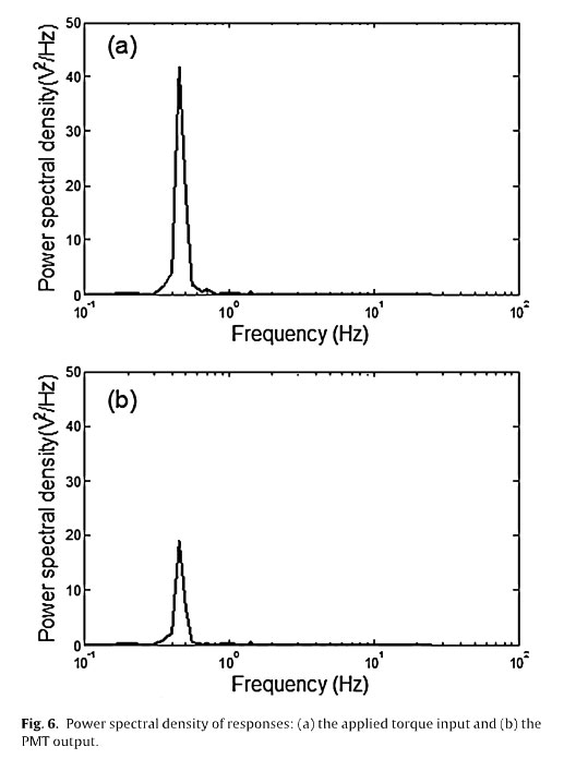
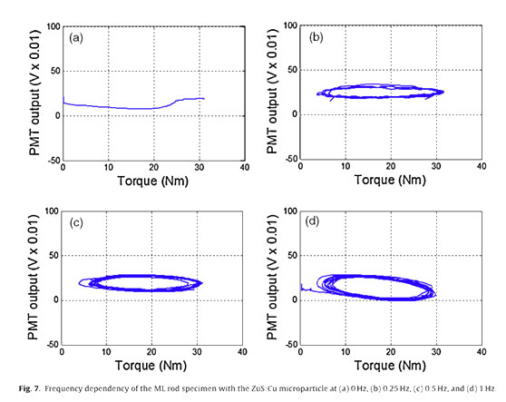
Fig. 6 indicates that no harmonic distortion caused by the nonlinearity of the measurement devices or second harmonic generation of the ML intensity is apparent, as reported in previous studies, because only the excitation frequency of 0.5Hz is dominant in the power spectral density (PSD) of the two signals (i.e, the torque input and the PMT output response) calculated using the fast Fourier transform (FFT). The PMT output of the ML rod specimen under sinusoidal excitation with three frequencies (0.25, 0.5, and 1 Hz) is investigated using hysteresis loops to identify the frequency dependency.
The ML intensity shows a variable hysteresis pattern that is nearly proportional to the excitation frequency, as shown in Fig. 7. Because of this hysteresis behavior, the instantaneous relationship between torque input and PMT output is highly nonlinear, and it is necessary to estimate the hysteresis model.
3. Loading Rate-dependent Hysteresis Model
In the present study, a semilinear Duhem model is first considered to capture the loading rate-dependent hysteresis behavior between the torque input and the PMT output. The equation under consideration is a first-order nonlinear differential equation. This equation has been developed to model magnetic hysteresis, but experiments have confirmed that this model is also suitable for modeling piezoelectric hysteresis. The model for the hysteresis phenomenon occurring between torque input T(t) and PMT output (ML intensity) M(t) is given by where Q> 0 and a> b> 0.5a are model constants depending on the shape and area of the hysteresis loops.
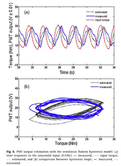
The PMT output M is considered to be the state variable of the differential equation and is dependent on both the applied toque input (T) and the rate of the applied torque (T). Using a numerical method (e.g., the Runge-Kutta fourth-order method), the nonlinear simulation of Eq. (3) can produce the hysteresis effect with torque measurement. Fig. 8(b) shows the comparison between the measured and the estimated Duhem model-based hysteresis loops between torque input T(t) and PMT output M(t). The parameters and constants are estimated to bea= 0.4,a= 1.2, and b= 0.8. Compared with the measured PMT output (ML intensity), the shape of the estimated hysteresis loop does not produce a strong match, which implies that the estimation based on the Duhem model captures the ML intensity measurement with a large error. To improve the accuracy, new ad hoc heuristic equation characterizing the ML intensity as a function of the rate of the applied torque input is suggested:
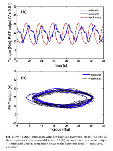
where a and b are constants. The estimated ML intensity with respect to the torque measurement fits well with the ML intensity measurement for the optimized constants (a= 0.2 and b= 20), as shown in Fig. 9. This simple heuristic model also captures the loading rate- dependent hysteresis effect with a small error when a constant torque input is applied, as shown in Fig. 10. These comparison results indicate that the estimate based on the proposed heuristic hysteresis model outperforms the Duhem hysteresis model.
4. Torque Estimation from ML Intensity Measurement
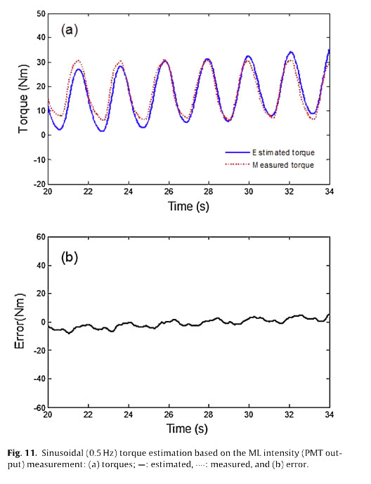
Based on this study's results, it is possible to realize new type of non-contacting torque transducer, as depicted in Fig. 11. The PMT sensor module will detect the ML intensity in response to the torque load. The output voltage of the PMT sensor module can then be amplified, filtered, and sampled through a digital signal processing and analog-to-digital converter (ADC). For example, in this study, using the MATLABR Signal Processing Toolbox provided by MathWorksTM, the sampled data is recovered by a second- order low-pass digital Butterworth filter with a cut-off frequency of 100 Hz and this process can be also implemented using an analog low-pass filter (e.g. a RC circuit). With the proposed heuristic hysteresis model, it becomes possible to build a torque estimation model to compensate for the hysteresis effect resulting from the PMT output measurement. The applied torque load can be estimated simply by integrating the PMT output based on the loading rate-dependent characteristic equation given in Eq. (4). The output voltage of the PMT sensor can finally be converted to the torque output applied to the rotational shaft.
The ability to estimate torque is numerically evaluated under the MATLAB/Simulink environment with a Runge- Kutta fourth- order solver(a=- 5, and b= 100 in Fig. 11). The torque estimation resulting from the PMT output measurement shows good agreement with the actual torque input signal T(t)= 20+ 10 sin(2π . 0.5t) Nm measured by a commercial in-line torque transducer. The root-mean-square (RMS) error is calculated to be about 4.2 N m (about 23 percent of RMS value of input signal).
5. Conclusion
The use of mechanoluminescence (ML) enables us to successfully measure the torque applied to the rotational shaft without contact. Inherent to an initial prototype torque measurement system based on a conventional microparticle (SAO), the ML intensity decay issue has been resolved using a new microparticle (ZnS:Cu). The loading rate-dependent hysteresis phenomenon of ML intensity emitted from ZuS:Cu was effectively modeled using an ad hoc heuristic hysteresis model consistent with experiments. Derived from the heuristic hysteresis model, torque estimation based on a simple compensation scheme demonstrates the feasibility of applying a non-contacting rotary torque sensor because the torque estimation shows good agreement with the actual torque [T(t)= 20+ 10 sin(2π .0.5t)N m] measured by a commercial in-line torque transducer. These experimental results demonstrate that it is possible to provide a non-contacting means of measuring the dynamic torque applied to a rotating shaft using a simple luminescent sensor (such as a PMT) and an UV light source. This study indicates potential applications for new non-contacting torque sensing technology, which is widely used in various industrial areas such as automotives, robotics, rotors, and turbines. The future direction of current research includes further analysis of the heuristic hysteresis model, in-depth study to mathematically formulate torsional stress induced ML intensity, hardware implementation of a rotary torque sensor using embedded software, etc. Acknowledgments This study was supported by the Basic Science Research Program through the National Research Foundation of Korea (NRF), funded by the Ministry of Education, Science, and Technology (NRF- 201 4R1A1A1004366 and 201 4R1 A2A2A01003275) and partly by the High-Tech Urban Development Program funded by the Ministry of Land, Transport and Maritime Affairs of the Korean Government (11-High-Tech-Urban-C02).