1 Overview
The torque parameter of the valve is one of the important parameters for valve design and user selection. The valve torque test system can provide the valve torque parameter and various factors that affect the valve torque. The reaction torque transducer in the system converts the strain generated by the torsional moment into an electrical signal that has a linear relationship with it according to the principle of resistance strain. The measuring range is 0~10000 Nm, the accuracy can reach 0.05%FS, and the performance is stable and reliable.
2 System Structure
The valve torque test system consists of valve torque monitor, reaction torque transducer, electric actuator, industrial computer, etc.
2.1 Valve torque monitor
The valve torque monitor is mainly composed of isolation transformer, DC-DC conversion module, data acquisition control module, switching power supply, signal and power connector and box. The three-phase four-wire power supply of the monitor is input into the instrument in two ways through the power interface. One input power control module controls the forward and reverse operation of the electric actuator. The other input isolation transformer provides power to the signal board and the interface board through the switching power supply. There is an emergency stop switch and a power indicator light in the main circuit. The torque signal passes through the DC-DC conversion module and then enters the data acquisition control module and is connected to the computer to realize the transmission and processing of the signal.
Because the power supply of the reaction torque transducer is a switching power supply, its power level is level3, the voltage regulation rate is 10%, and the load regulation rate is 0.5%. When the system is working, the output voltage of the torque transducer signal terminal fluctuates by 0.54V and the frequency is 50Hz, which causes the data collected by the host computer to be unstable. After analysis, the power supply performance of the torque transducer is improved by adding a power isolation module. After adding the power isolation module, the output voltage fluctuation of the torque sensor is very small, about 0.05V.
2.2 Torque transducer
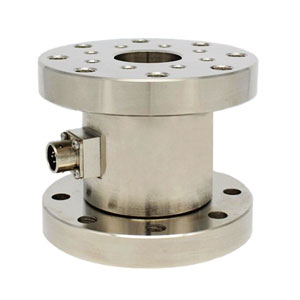
The torque transducer adopts double flange reaction torque transducer 10000 Nm, which has stable structure, good coaxiality and strong anti-overload ability. The full-scale accuracy of the transducer is grade 0.5, and the 2-wire 4~20mA signal is used. And no separate calibration is required.
The reaction torque transducer is made using the principle of metal strain (the resistance value of the metal will change when the metal is subjected to external force), and the metal bridge is built into the sensor housing. The resistance of the bridge will increase or decrease under the action of axial torsion. When the input end is applied with a DC voltage, the output end can obtain a voltage signal that change with the magnitude of the applied force. Then, the corresponding current signal is output through the signal processing circuit.
2.3 Industrial computer
The system uses a high-reliability PSCE-2000 industrial computer, which can work in complex industrial environments such as dust, smoke, high/low temperature, humidity, vibration and corrosion, and has rapid diagnosis and maintainability. Its MTTR (Mean Time to Repair ) is generally 5min, and the MTTF can reach more than 100kh. In addition to excellent real-time, expandability and compatibility, the computer can work continuously for a long time, the special power supply in the chassis has strong anti-interference ability, the special bottom plate in the chassis has PCI and ISA slots, and the chassis adopts steel structure. It has high anti-magnetic, dust-proof and shock-proof ability. The upper computer software of the system is written by Visual Basic software.
3 How It Works
The system loads the valve through the hydraulic pressurizing equipment, and the industrial computer runs the upper computer test software to control the opening and closing of the electric actuator, monitor the valve torque and stroke status, process the collected torque and stroke data and display it in real time to achieve Tables and curves are saved on the hard disk, which is convenient for users to analyze and calculate. The instructions from the industrial computer are input to the valve torque monitor through the shielded cable. The monitor is converted, amplified, filtered and isolated and sent to the electric actuator through the signal cable. The torque signal, valve position and operating status of the valve are fed back to the signal conditioning module, after processing, input into industrial computer to complete related calculations.
4 Torque Verification
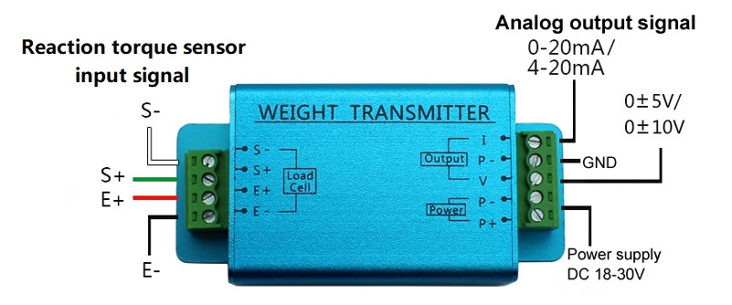
The accuracy of the reaction torque transducer in the system is 0.05%FS. The torque signal is sent to the torque sensor transmitter 4-20mA through a shielded cable, and its accuracy is 0.05%FS. Therefore, the maximum error of the system torque should not be greater than 3%FS. In order to verify the torque error of the system, gradually load the test valve, and use the reaction torque sensor and the tension-pressure sensor to read the valve torque data at the same time. The verification result shows that the maximum error is 2.71%, which meets the requirements.
5 Conclusion
The reaction torque transducer with high precision, fast frequency response, good reliability, long life and good explosion-proof performance is applied to the valve torque test, and the method of adding a power isolation module to improve the power performance of the torque transducer not only saves costs, but also guarantees system reliability.